What Optics Do You Need for Your Lidar Development?
These days almost every optics magazine seems to have articles covering some aspect of lidar systems. Lidar, or LiDAR if you prefer, is the acronym for Light Detection And Ranging and sees applications in fields such as topographic land mapping, aerial inspection, agriculture and defense. The big growth area we’ve seen in recent years has been automotive and industrial robotics, which are both under the umbrella of autonomous vehicles. These are demanding environments, especially automotive, from the point of view range, temperature, reliability and cost, but it has still led to an explosion of start-ups entering the arena. Traditional lidar systems used mechanical scanning to build up the image. More recently solid-state versions use a 2D array of VCSELs which simultaneously illuminate the scene via a transmit lens and then capture return photons via a receive lens on a detector array that spatially matches the VCSEL array. These offer a much more robust and cost-effective solution than scanning systems. Normally the transmit and receive lenses are identical so that the emitted photons, after reaching a target, make an identical return journey to the matching detectors and any lens distortion on the way out is cancelled on the way back. There is little bit of parallax caused by the offset in optical axis between the emit and receive channels.
The key capabilities of Lidar developers are in sensors and software. At some point in the development they need to attach lenses to the system and that’s where Selene Development comes in. Specializing in the supply of custom lenses, we have supported a number of lidar start-ups in their system developments.
If you are developing a Lidar system you will probably want to start with some off-the-shelf lenses for laboratory development. There are some top-level requirements for lenses that are obvious.
- The system will work in the near infra-red, usually somewhere around 900nm (to match the source lasers) which means you will look for a standard catalog lens (probably c-mount or similar) which is advertised as VIS-NIR (which will be from about 400nm to 1000nm).
- You will have a field of view requirement.
- You will have a sensor size requirement and you’ll find catalog lenses are available in standard ½”, 1” formats etc. (where ½” means 8mm diagonal, 1” means 16mm diagonal). You might not find a format that is ideal for your sensor.
- Finally, you will also want a low f-number (as low as possible) to capture as many photons as possible and you will probably find that f/1.4 is about as low as you can go.
This can lead to the procurement of a reasonable lens for in-house development but not ideal for customer trials. Such a lens could be something like this below. This is an example f/1.4 VIS-NIR camera lens.
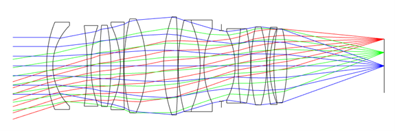
This layout reveals some less obvious requirements of a lidar lens where this lens falls short.
- F-number: the blue bundle of rays shows you what f/1.4 looks like. However, the red rays are nowhere near f/1.4. The lens designer has utilized vignetting in the design. This is very common in lens design and is used to remove troublesome aberrated rays which occur at larger fields. It is achieved by intentionally clipping the rays on certain elements. In this case the front and back lens elements limit the red and green rays. In this view the red and green cone angles are limited by the bottom of the front element and the top of the back element. The consequence of employing vignetting in lens design is to reduce image brightness towards the edge of the sensor. This might be fine for a camera lens but is usually NOT desirable in a lidar lens which is usually starved of photons and so will reduce the system range performance towards the edge of the field.
- This off-the-shelf lens is not telecentric. The red cone of rays is not parallel to the blue cone. Again, this is typical for a lens where telecentricity is not specifically required. For a lidar application where identical transmit and receive lenses are used the VCSEL array will emit parallel cones of light. Imagine rays being emitted (and going left) from where the red rays focus. Even though the VCSEL cone angle may be +/-10° of so you will lose some of the light on the output path.
- The lens will almost certainly not be athermal; the focus will drift with temperature. That is OK with a camera lens which has a focus adjustment, and you can adjust to best focus in the lab. But in the field, you need a lens which is fixed (no focus adjustment and no aperture adjustment either).
- The anti-reflection coatings on this lens are wide band and will probably achieve about 0.5% reflectance. Custom coating designed for one wavelength (and the specific angular range of a custom lens) will achieve about 0.05-0.1%. If you calculate the transmission, it will be similar in both cases, but a custom coating greatly reduces stray light artefacts. The difference in double reflection power between 0.5% and 0.1% coatings is 25x.
One parameter where this lens does not fall short is resolution. Lenses of this type are designed for camera sensors with pixels of a few microns square. I have designed lidar lenses for detector arrays with 10µm pixels, 50µm pixels and even 1mm pixels (if you can call a 1mm square detector a “pixel”). Resolution is the one parameter that can be relaxed in a lidar lens to make the simpler and, critically, low cost. A larger pixel means lower resolution, fewer elements and lower cost.
The only other parameter which makes the lidar lens designer’s job easier is the light sources are diode lasers which are monochromatic, and not having to achromatize the lens for a wide spectrum simplifies the design. However, the designer will need to consider the laser wavelength variation off the production line and that the wavelength of the lasers are temperature dependent. This is built into the athermalization process.
After the phase of laboratory proof of concept, the lidar developer will probably make the jump to a custom lens designed specifically for their detector, field-of-view, etc. What they will receive is likely to be something like this lens below.
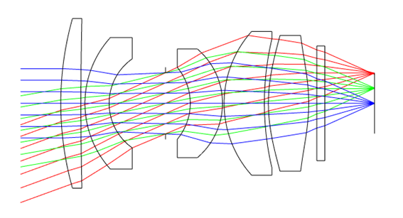
It may be more or less complex depending mainly on the pixel size, but also on the field-of-view, f/#, and detector dimensions. The characteristics of this lens can be summarized as:
- Low f/#, in this case f/1.1.
- Designed with a minimum number of components. The lens needs to be very low cost.
- Probably includes one aspheric lens. This will be molded which adds some design constraints. The glass, of course, needs to be a moldable (low glass transition temperature) material, and molding comes with design rules on thickness, aspect ratio etc.
- No moving parts.
- No vignetting. Similar photon collection efficiency across the field.
- Telecentric.
- Includes a thin glass window to represent a narrow band filter to minimize background light reaching the detector array.
- Athermal design to maintain focus over a wide temperature range.
- Robust. Shock and vibration should not impact boresight stability.
In switching from off-the-shelf to custom lens, lidar developers will see a noticeable difference in the system performance, especially in stray light and performance across the field. If you are in the process of developing a lidar system Selene Development can support your development efforts from the beginning (providing appropriate initial off-the-shelf optics) and throughout your development with custom optics in volumes from prototype to full production via our manufacturing partners. For further information contact Ian at: ian.wallhead@selenedev.com