How would you like your distortion, rectilinear or curvilinear?
If you want to commission a custom-designed lens you need to define your specification. There are straightforward parameters, like field of view and resolution but a tricky one to specify is distortion.
There are two main forms of distortion, rectilinear and curvilinear. Rectilinear is what most people are more familiar with. It is based on a lens which mimics the imaging you get from a pinhole camera as shown below.

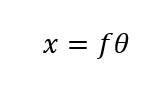
The object points transform to the image points according to the equation:
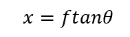
The parameter x is the radial position of a projected point on the image plane. The notional focal length, f, is the lens focal length (or the distance to the image plane for a pinhole camera). The angle, θ, is the object space angle. With a pinhole camera this is the same as the corresponding image space angle and so the ftanθ relationship is obvious from basic trigonometry. This is rectilinear projection because straight lines are imaged as straight lines. It is also called gnomonic projection and is analogous to gnomonic map projection.
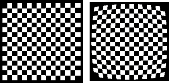
Most camera lenses with a small field of view aim to achieve this type of projection and deviation from it is described as ftanθ distortion. You will often see this type of distortion presented on a checkerboard pattern like those below. The left image is from a lens with zero ftanθ distortion, the right image is from a lens with 41.6% ftanθ distortion.
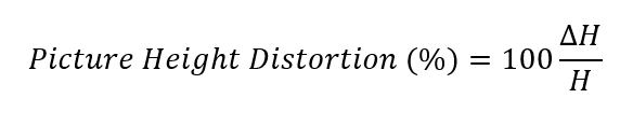
How is it actually calculated? The equation to determine distortion is:
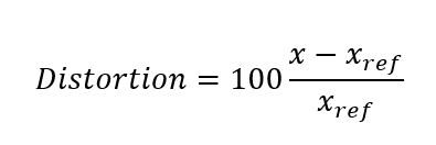
Where xref is the radial position on the image plane where the ray should land, in this case given by ftanθ, and x is where the ray does land. Where rays land is seen in the following plot and the corner ray x and xref are highlighted.
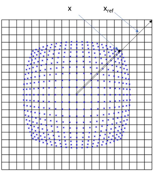
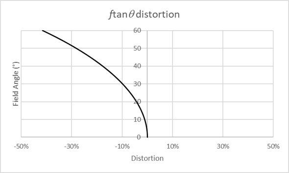
This corner field point has -41.6% distortion. Barrel distortion like this is negative, pincushion is positive. The distortion is not a single value, it varies across the field (see plot below). In this example the maximum distortion occurs at the maximum field but that’s not always the case.
ftanθ is one way of describing rectilinear distortion. TV distortion is another way (in fact another two ways as we’ll see) of describing distortion.
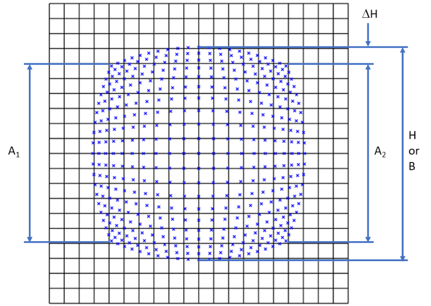
TV distortion was traditionally defined (for example by the European Broadcasting Union) as:
More recently Standard Mobile Imaging Architecture (SMIA) standard defined TV distortion as:
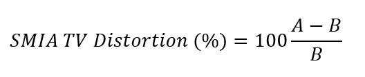
Where A = (A1 +A2)/2.
Both definitions are labelled on the above figure, and you will see that SMIA TV distortion is twice as large as traditional TV distortion. For this example, traditional TV distortion is -8.8% and SMIA TV distortion is -17.6%.
So, the same lens can be described as -41.6%, -17.6% or -8.8% distortion depending on the definition, and all are referring to rectilinear distortion. You have to be careful you know what you are specifying.
What about curvilinear distortion? Curvilinear distortion is an umbrella term applied to the various types of distortion commonly used in wide angle or fisheye lenses. The figure below shows the main types. This figure is copied from an article by Bettonvil1 and this article explains nicely the subtle differences between these types of fisheye lens. The most important is the equidistant fisheye which is a straight line on the plot. This means the position that rays reach the image plane are proportional to object space angle (not tangent of the angle). In other words:
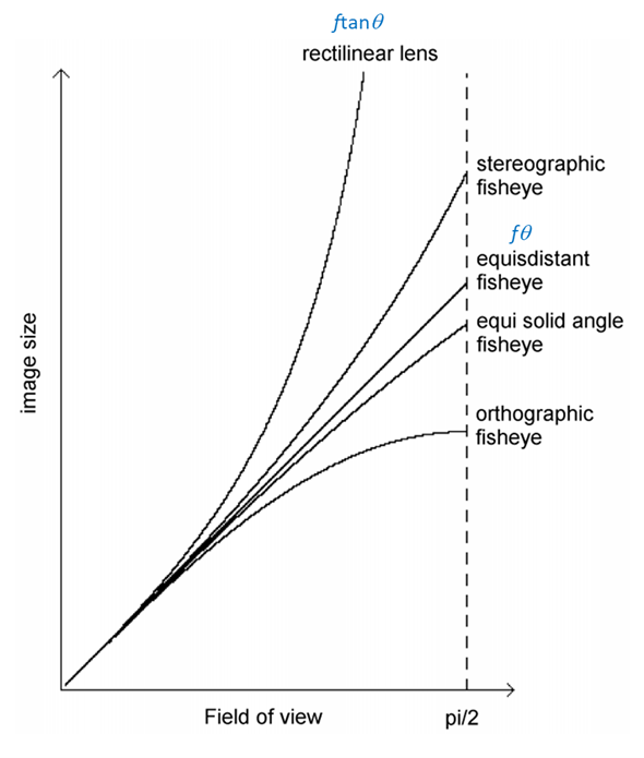
Lenses designed to this model are described with fθ distortion. It becomes increasingly difficult to design ftanθ lenses with large fields of view and of course ftanθ becomes nonsensical at 180° field of view. But it’s not used simply because it’s easier for wide angle lenses to be designed as fθ. There are important imaging properties.

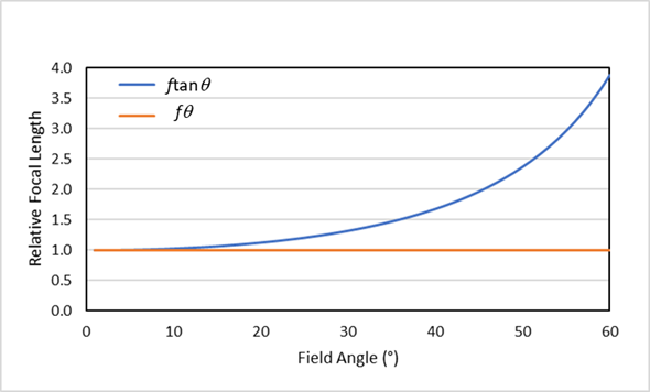
If x=fθ then this implies that any dθ in the field corresponds to the same dx at image plane. What this means is that the lens focal length is constant across the field. It may not be obvious, but this is not the case for ftanθ lenses (see plot below). When a lens focal length is given, it refers to the focal length on axis. In fact, the equation x=ftanθ is the very definition of focal length. Since we are only considering rays very close to the axis tanθ =θ so either equation applies in practice. When a lens has distortion it means the lens focal length deviates from these lines across the field.
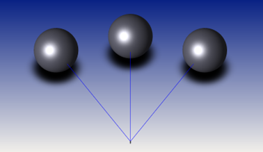
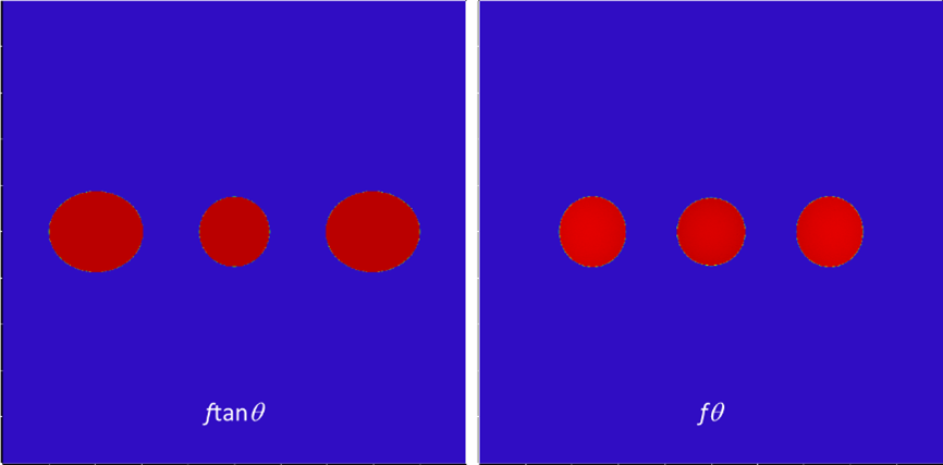
The relevance of this is that the image of objects like this below (three identical spheres positioned at the same distance from the lens) would be better imaged with an fθ lens. An ftanθ would distort the end spheres.
Below is a simulated image of the spheres with an ideal ftanθ lens and a pretty good fθ lens (with about -3% fθ distortion). An example where you might want to specify an fθ lens could by a LIDAR lens you get a return signal from objects over an angular range but up to a fixed distance.
Here is a real example taken from a paper by YiChang Shih et al2 showing exactly this effect. The straight lines in the background are well imaged but the faces at the edges of the field are distorted.

Without some sort of software correction, you can’t image both types of objects without distortion at the same time.
So, a lens with very good ftanθ correction will give you good images of planar objects like the checkerboard pattern, but distorted images of objects placed radially around the lens. A lens with good fθ correction will do the opposite.
You may be interested to know that the fθ simulation above is with the very same lens described as -41.6%, -17.6% or -8.8% rectilinear distortion (depending on the definition). So we can now add -3% distortion to the list of possible definitions!
Another example where fθ lenses are common is scan lenses (like the one shown below) which are often used in laser marking, micromachining, and hole drilling.
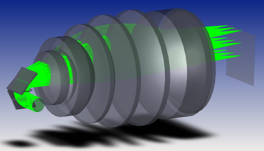
In this case you want to position the laser spot on the workpiece according to cartesian coordinates and having an fθ lens allows you the convenience of having a direct angular input to the galvanometer mirrors.
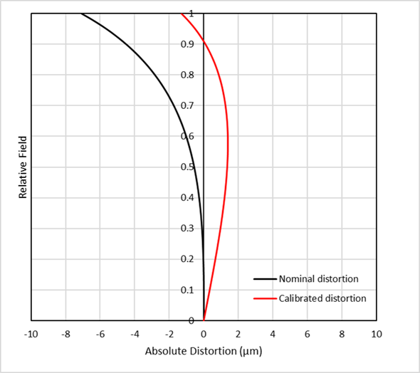
There is one more definition of distortion that is worth mentioning. Consider a lens used for relaying a pattern on an object such as a mask to an image plane, for example in microlithography or in some laser micromachining applications. In this case you usually want to specify the distortion not as a percentage but in absolute terms, i.e. in microns. For example, you might want the features on the workpiece to be within 2µm of where they should be. Look at the graph below. The black line represents the position error (ie distortion) of features on a workpiece or wafer. The position error on axis is, by definition, zero. Close to the axis the position error is still close to zero, but it reaches 7µm at maximum field. This would appear not to meet the 2µm requirement. But we can represent the same data in a different way. If we simply assume a slightly different focal length (or magnification) the data does meet the specification. This is the red line, which you can see has an absolute distortion of less than +/-2µm across the field. We call this calibrated distortion, and it can be expressed in percentage or absolute terms.
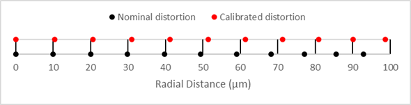
For this type of lens the optical designer would aim to design the lens at the specified magnification but with the red line distortion plot. What this looks like in ray position error is shown below (but grossly exaggerated to see the effect). The black dots should appear on the vertical lines but they gradually creep left until the last dot is 7µm short of the 100µm ideal location. If you imagine the black dots are connected by an elastic band, you could pull the last dot and stretch the band until you get a good balanced position of dots which would be where the red dots are.
Hopefully this has given readers a brief overview of what to specify and also how to compare different lens specifications. It’s easy to get it wrong and to misunderstand data you’ve been given. Give us a call to discuss your custom lens requirements.
- Felix Bettonvil, Fisheye lenses, WGN, Journal of the International Meteor Organization, vol. 33, no. 1, p. 9-14, 2005
- YiChang Shih, Wei-Sheng Lai, and Chia-Kai Liang, Distortion-Free Wide-Angle Portraits on Camera Phones, ACM Trans. Graph., Vol. 38, No. 4, Article 61, July 2019