Etendue of a Fly’s Eye Illuminator
In the first blog article I introduced the subject of étendue and its importance in illumination systems. The example used was simple optical relay, but many systems utilize fly’s eye arrays to provide homogenous illumination. What is the impact of splitting a beam into smaller beamlets on the étendue?
Consider this system…..
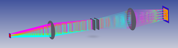
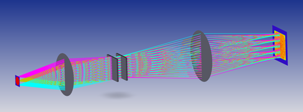
On the left is a 10mm diameter light source which is emitting over 0.11NA. The illumination plane is 30mm square and the illumination NA is 0.12. The grey circles represent ideal, aberration-free lenses and in the center of the system is a pair of fly’s eye arrays. For convenience the system is telecentric at both source and illumination plane.
The system works well in converting a circular source to a square illumination plane with the required NA. So, what about étendue? In the previous article étendue was defined using two equations, an integration over an area and a solid angle, and an approximation which is valid for low numerical apertures:
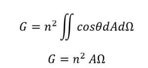
In this case the approximate equation is OK, and we can ignore the n2 since the refractive index is 1.
If we calculate the etendue at the source, we get 78.5mm2 x 0.04sr = 3.1mm2sr.
The same calculation at the illumination plane gives 900mm2 x 0.045sr = 40.3mm2sr
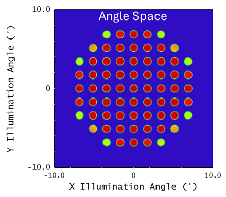
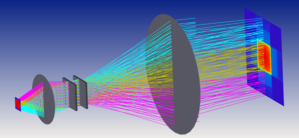
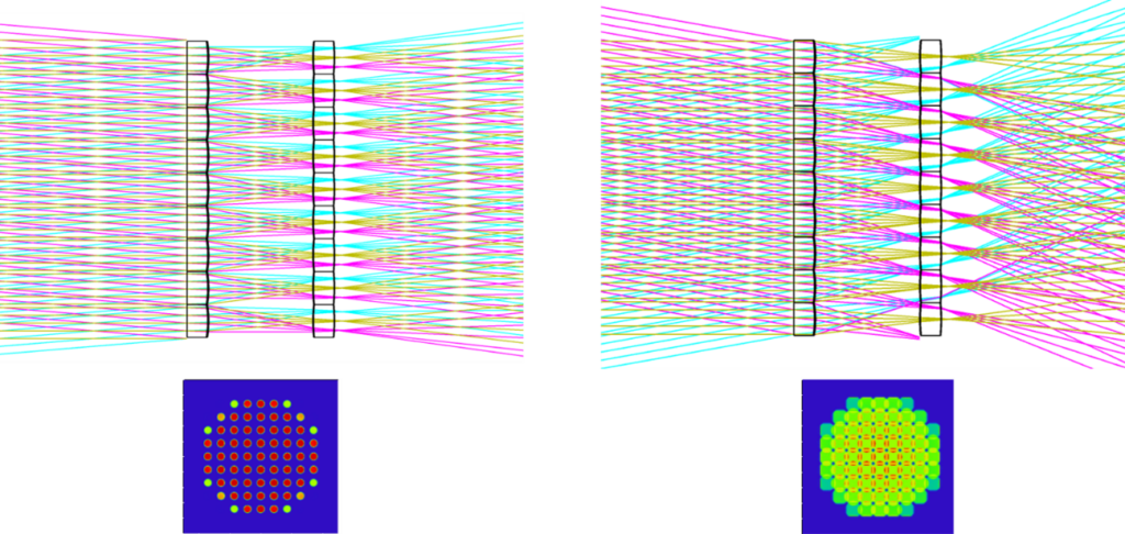
These values are nowhere near the same so what’s going on? Has the fly’s eye increased the étendue by more than 10x? To answer this, we need to look in detail at the illumination plane. The figure below shows the optical simulation of the illumination plane. The left figure shows the typical irradiance plot in position space. The right figure shows radiance which has unit of watts per steradian per square meter. This is an angle space parameter. This plot shows that the illumination plane is illuminated from a discrete set of angles, each with a small solid angle.
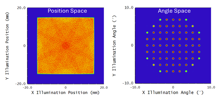
If we zoom in to the angle space plot we can estimate the angular range at each spot to be about 0.48° diameter which corresponds to 5.5×10⁻⁵sr. In this optical system the arrays are 9×9 with the three lenslets at each corner removed. This means there are 69 spots in the radiance plot. For this optical system we should rewrite the étendue equation as:
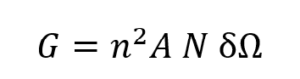
Where N=69 (the number of lenslets used in each array), and dW is the solid angle of each spot.
This generates an étendue of around 3.4mm2sr at the illumination plane. Given this is an estimation, I think this is close enough to the source étendue to conclude that in a fly’s eye illuminator étendue is actually conserved. We could say that the 40.3mm2sr is the apparent étendue.
What does this mean for the power efficiency of a fly’s eye illuminator? In the previous article I concluded that in many illuminators you simply cannot utilize the full etendue that the source offers. In this case, the fact that we are underfilling the angle space plot tells us we could be receiving more power at the illumination plane. Let’s try using doubling the NA at the source to collect more light, as shown below.
The illumination size is unchanged at 30mm square, and the NA is also the same. The angle space radiance plot has changed though.
We can see that the spots are larger. The diameters have doubled to 0.96mm and so the etendue is 4x higher. This brings the etendue to 13.7mm2sr which is about 1/3 of the 40.3mm2sr. This is a more power efficient system than the original.
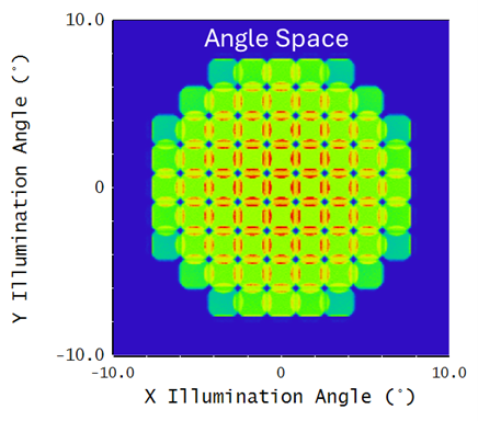
Now let’s double the source NA again (see below). The illumination area and NA are still the same, but we see some additional illumination outside the main area.
Let’s look at the radiance plot for this system (below). As you can see, the illumination spots are so big they are overlapping. We are now overfilling the angle space illumination. What does that mean?
If we zoom in on the ray layouts of the last two systems, we see that overfilling in angle space corresponds to rays missing the correct lenslet in the array. These rays subsequently reach the illumination plane outside the illumination zone which are, of course, lost. In the left plot, even extreme rays reaching a particular lenslet in the first array all continue to the corresponding lenslet in the second array. In the right plot the extreme field rays fall into the neighboring lenslet.
So, in conclusion:
- For fly’s eye systems with very low etendue sources (e.g. laser micromachining) we can simply design for an apparent étendue at the illumination plane. We can be confident that we are not losing light due to étendue issues. There are other considerations for fly’s eye systems with lasers but we won’t go into those here.
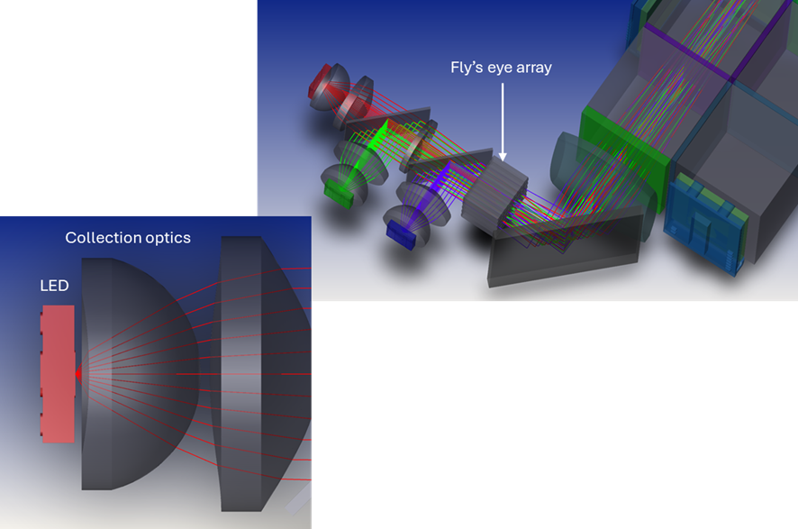
- If we are designing a fly’s eye illuminator and we are interested in throughput efficiency, we need to optimize the illumination plane radiance fill factor to get the étendue as close as possible to the apparent étendue without overlapping in angle space. We then need to design optics to collect light from a source such that we match that étendue. In practice this often means specifying as small a source as possible (low cost, low power, compact) and then designing optics to collect as much of that light as possible. An example of such a system is shown below.
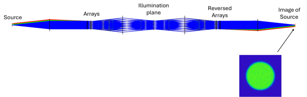
One final point, I said fly’s eye array systems maintain étendue. We can confirm this by removing any screen or object from the illumination plane and adding a reversed version of the same optical system to get an image of the source. It should have the same étendue as the original source. The layout below shows this. This cannot be achieved with, say, a diffuser in the optical system which would increase the étendue.
If you need optical design support for your illumination project Selene Development is here to help.