Image Relay Beam Expander
Surely virtually everyone who has worked with lasers has used a beam expander. There are two basic types, as shown below (you can also use mirrors or prisms):

Sometimes there is a special case when you want the expander to do two things: expand the beam and also provide a relay between conjugate planes, ie from an ‘object’ plane to an ‘image’ plane. This is often done without an expansion, or in other words, with a 1x expansion. People may know this as a 4F system, shown below.
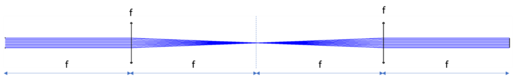
The system has two lenses of focal length, f, with separations of four focal lengths throughout the system, hence the name. You can see the imaging nature of the system if we add some field angles.
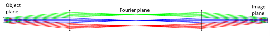
This system might be used in which an object is illuminated and the Fourier plane is used to spatially filter the light that reaches the image plane. I have also used this to relay the output from an excimer laser in micromachining applications. Excimer lasers have high divergence and are often located a long distance from the micromachining workstation for safety reasons. The laser itself may be located in a separate room such as a cleanroom service corridor as it requires the supply of a toxic gas such as chlorine or fluorine.
In this application the object plane will be the laser output window (or somewhere within the laser tube) and the image plane may be the input of a fly’s eye homogenizer group or similar. The total track length between the laser and the homogenizer may be a few meters. This type of beam delivery system works well to overcome the effects of the large divergence over the long track length.
What most people don’t know is that this basic concept is very flexible. It doesn’t have to be 4F. In its 1x mode the two lenses can, as a pair, slide up and down the track length while retaining both the 1x expansion and the fixed imaging all within the same track length. You can see this in the layouts below.
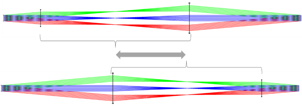
It can also be set up to have a beam expansion other than 1x.
For the general case with any expansion ratio the relationship between the parameters is given by the following equations. I won’t go into the detail of the derivation since I derived these about 20 years ago and my notes are archived…somewhere!!
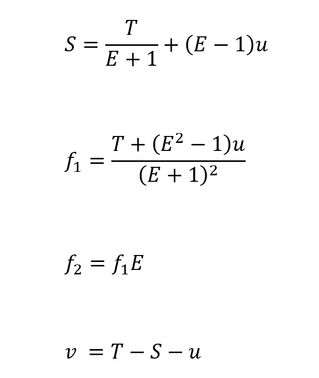
Where:
S is the separation between the lenses
E is the expansion ratio
T is the total track length
f1 and f2 are the lens focal lengths
u and v are the working distances in object and image space respectively
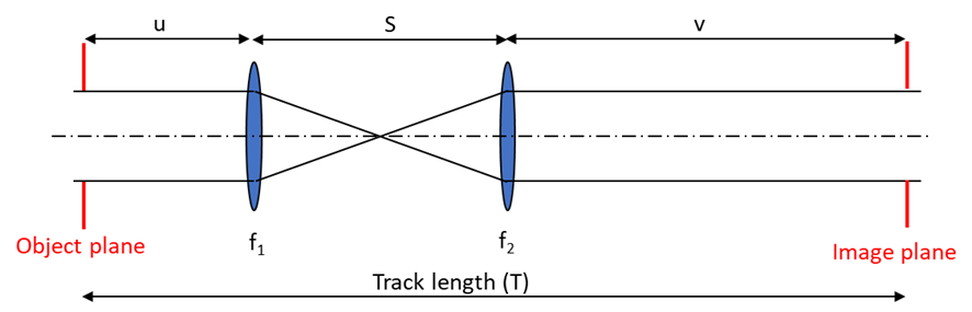
The last two equations are trivial but, together with the first two, enable you to set up the system. It is assumed that the starting point is that you have an available track length (T) to work within, a required expansion (E) and the object space working distance (u).
You will notice that in the first two equations the working distance (u) is multiplied by (E‑1) and (E2‑1). Hence, when E=1 the focal lengths, f, and separation, S, are independent of u. This shows analytically why the pair of lenses can slide up and down the track length as we’ve just demonstrated.
Now consider a general example. Let’s say you have 400mm of track length available. You want a 3x expansion and you can put the first lens 20mm from the object plane. Applying the 4 equations gives:
f1 = 35mm
f2 = 105mm
S = 140mm
v = 240mm
Putting this together the system looks like this:
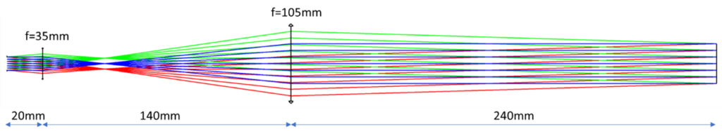
You can see the 3x expansion and the conjugate relay works perfectly!